The Delta Loop (Skywire) Antenna
Legends, Theory and Reality
Summary
Karl, DK5EC, describes the construction of a simple multiband delta loop antenna (skywire) for the 80m - 10 m bands. The construction will be theoretically initialized with the help of the antenna calculation program EZNEC, and later measured and graphically documented with the inexpensive antenna analyzer miniVNA. Furthermore, the advantages of a coaxial cable in comparison to an open feeder line with matchbox will be verified by practice and measurements.
Motivation
Since a few weeks, I enjoyed working on the shortwave bands again after being QRV primarily on the VHF/UHF bands working via satellites, the ISS and moon (EME). For shortwave operation I do have an 18m Versa Tower and a 3 element beam for 10/15/20m. Recently I started operating mainly on 20m since 10m and 15m were practical dead. I noticed that 20 m also was very quiet after 19.00h local time. I did not put up anything for the lower bands, since I did not miss them because of my preference for the VHF/UHF space activities.
In the mean time my preferences have changed, and I had to do something for the lower bands. A few weeks ago the antenna analyzer fever infected many members of our radio clubs because even low budgets hams can afford them for around € 250, and can do a lot of interesting things with them. Hence I decided, not only to construct the antenna but to consider it theoretically with the antenna calculation program, to measure it after construction with the antenna analyzer, and finally to compare theory and practice.
Theoretical Preparations
After having repaired our delta loop antenna of our radio club, and being very fond of the simplicity and efficiency of this antenna, I decided to build a similar antenna at home. First I informed myself in the Rothammel and ARRL Handbook. The Rothammel is not very informative about this antenna type, it describes some vertical loops, i.e. cubical quads. The internet also gave me some ideas, partially with contradictory legends which made me nosy. The best description I found in the ARRL Handbook.
I couldn't find the expression "delta loop" in the ARRL Handbook, but it describes a similar construction using the name Loop Skywire. It was described here as a very underrated secret concerning the cost/yield relation. Afterwards, I had to agree to that statement completely. The antenna was supposed to be a multiband antenna without traps and coils, fed with a normal RG58 coaxial cable, and practically doesn't cost anything. It is supposed to be resonant at the base frequency 3,5 MHz and all multiples, that is at 40, 30, 20, 15 and 10 m. The Handbook furthermore states that a perfect radiation pattern can be achieved with a circle shaped loop, but because of the many necessary supports it would be hard to construct. A square shape is a compromise and needs only 4 supports. Also other shapes are possible, that is with certain restraints, the Handbook said.
The next step was a site survey at my backyard. Since my backyard is encircled by high trees, a square shape as described in the Handbook would have been to difficult to put up because of the absorption problems of the nearby trees. So I decided to build up a Delta Loop, that is a triangle shaped wire. According to the potential supports, a triangle with about 30x30x20m would be possible, fed with a coaxial cable in one corner of the triangle, that is, using the Versa Tower as a support. The 2 other supports would be at the TV antenna mast on top of my house, and a high pine tree at the back of my yard.
The Delta Loop of our radio club uses open feeder line and a huge matchbox which were functioning great, but I wanted to avoid them because of the following reasons. Because of the metal tower and the problems getting it through the radio shack's walls the open feeder line would have posed too many problems, neither I owned a big matchbox. I decided to use the coaxial feed, as proposed in the Handbook. I will describe the measuring results of my coaxial fed loop with those of the loop with the open feeder line for comparison, with very interesting results.
Next, I had to determine the overall length of the wire. To do that I downloaded the antenna calculation program EZNEC from the internet. Since a loop antenna is most probably the most simple antenna type besides the dipole, I was able to enter the necessary parameters, after studying the excellent introduction of the program, without any doubts and problems. For this simple antenna, the freeware version of EZNEC with the limited number of measuring spots (segments) was completely sufficient. EZNEC takes into consideration different ground conditions, height of supports and wire diameter. I expected the EZNEC results more precise than calculating the wire length with the normal formula with c, f and k.
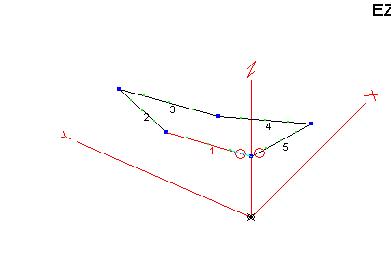
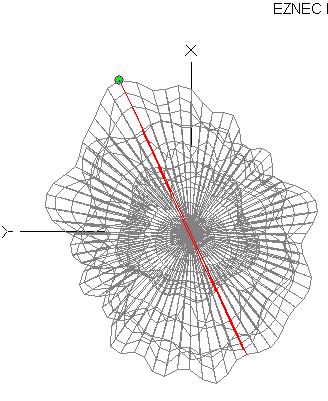
Now, EZNEC asks to enter the wire supports into a three-dimensional coordinate system. Considering my real estate the Y-axis is a parallel line to the eastern border of my plot, and the Y-axis parallel to the northern border. The Z-axis is equal to the height of the wire supports, one of them being the Versa Tower as a starting and feeder point. Both pictures below have the same meaning. I could move the left one looking as a two-dimensional picture, seen from the top or bottom, the right picture seen from the side. The 2 small circles being the feeding point. It is very simple with EZNEC to move these pictures into the desired angle of the beholder.
--------
EZNEC automatically generates these pictures above after having entered the data into the table "Wires". I divided the 2 longer wires into two halves in order to simulate the sagging of the wires. Hence I divided the antenna into 5 wires, even though it consists out of a single wire of about 86 m. Wire No.1 with its end End1 has been fixed to the Versa Tower (X=0m, Y=0m, Height Z=15m) and ends at the sagging point End2 at X=5, Y=20, Height=6m. End2 of wire No.1 is identical with End1 of wire No.2, etc. In the column Conn, the connection points are generated automatically, i.e. W5E2 at line 1, that is, wire No1/End1 meets wire5/End2. Column Conn is also a verification that you have entered all ends correctly.
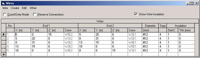
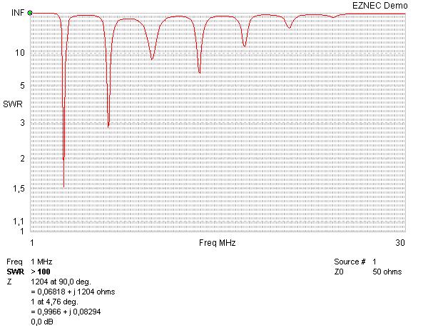
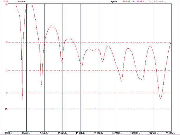
That's about all you have to do in order to start the calculations and to display the results. Via the button SWR you can display the resonance points of the complete antenna, as shown below.
The diagram shows very nicely the resonances at 3.6 MHz and its multiples. In the beginning I entered 30 m as a value into the above "Wires" table, without having calculated the actual length with the known formula. I noticed that I wasn't too wrong. I only had to add 1 m to the 30 m in the table, and it resulted into the desired resonance according to the SWR diagram. The actual lengths of the 5 wire segments are shown in the coordinate systems above when moving the mouse over the respective segment. The length of the complete wire would be then 86 m.
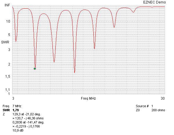
The above SWR diagram had been calculated with the assumption of 50 Ohms impedance at the feed point of the antenna. At 3.6 MHz I actually had excellent values with an impedance of 56 ohm and an SWR of 1:1.5. At 7 MHz it showed the theoretical impedance of 128 Ohm and an SWR of 1:2.8. That is, both bands could be operated without an further impedance matching. I repeated the same calculation with the assumption of an impedance of 200 Ohm at the feed point, hoping that the SWR values for the higher bands would improve, see the diagram below.
Indeed, the values for the upper bands improved a lot, but the SWR at 80 m got worse. Since I preferred the operation on 40/80m, I decided to connect the 50 Ohm cable without any impedance match or balun at the feed point of the antenna.
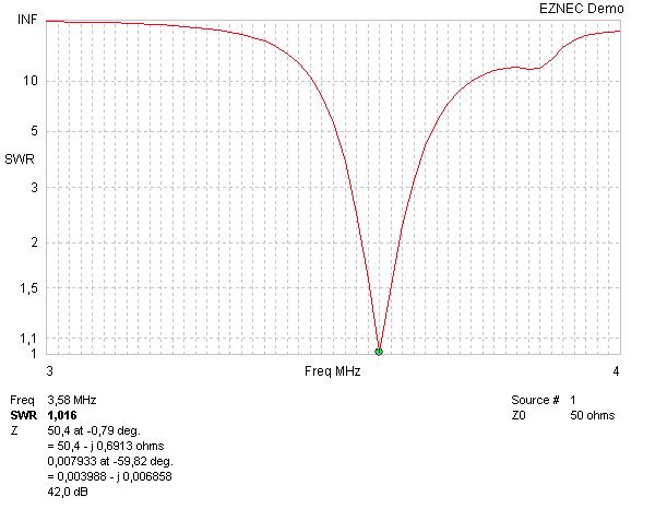
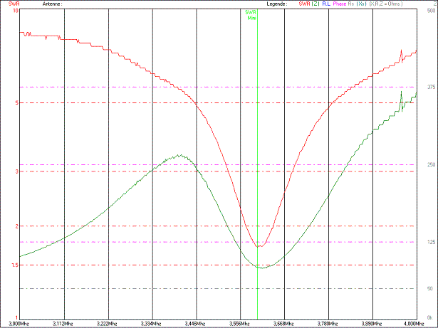
The diagram shows a rather narrow bandwidth of the two favored bands. The next diagram shows the range 3 - 4 MHz at higher resolution. Because of this better resolution we can see the near perfect impedance of 50.4 ohms and SWR of 1:1. The band width for SWR better than 1:2 is only a mere 45 kHz.
At 40m the result is similar, however with worse but acceptable SWR :
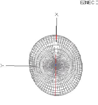
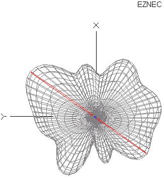
In the following pictures you will see all calculated radiation patterns, that is for elevation at the left and for the azimuthal direction at the right. Considering the rather low height of the antenna, it radiates preferably 90 degrees into the sky at 80m, having 3 dB less signal strength at 45 degrees elevation. All in all the loop operates like an omni-directional antenna, the difference between highest and lowest radiation levels at azimuth is only 3 dB.
Radiation pattern at 80m
-----
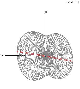
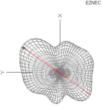
In order to get an overall impression, you can see the plots for the 40, 30, 20 and 10m band, showing already obvious directional characteristics. The higher the bands the flatter becomes the radiation as well as the numbers of side lobes.
Propagation Pattern at 40m
-----
Radiation pattern at 17m
------
Radiation pattern at 20m
----
Radiation pattern at 10m
------
And now the Reality and Practice
After having studied the theory, I now began with the construction of the antenna. As the ARRL handbook already mentioned, the antenna did not cost a single cent since I had everything available in my junk box. The 3 antenna supports were already present: the Versa Tower, the short mast of the TV antennas on top of the house roof, and the pine tree. The latter one even had a rope which I shot by arrow over the top a few years ago as a support for a longwire antenna. A 1:1 balun for connecting the coaxial cable, flexible 1.5mm wire, isolators as well u-clamps were also available from the junk box. The RG58/U to the top of the Versa Tower had been already installed since I used it many years ago for a VHF/UHF discone antenna.
The ex longwire could was enough for about half of the loop, the rest I found at the attic. I took the results of the EZNEC program to have an idea of the complete wire length, and I measured the 86 m with my step length. A long step with my rather short legs equals 1m +/- 20 % (more minus). I expected to be totally wrong at the first try since I could not enter the values for the ground conditions of my backyard with any precision, just guessing. Anyway, my legs told me that I measured about 80 to 90 meters.
My Versa Tower, fixed to the wall of my garage, can be lowered to about 7 - 8 m. The top of the house roof is about the same height so that the antenna wire touched the roof with the tower in its lowest position. At the side of the pine tree I pulled the loop edge to the highest possible position, about 9 m. And before I cranked up the Versa Tower which takes quite a bit of energy out of that old man, I intended to make a provisional measurement. Right in time DL9NDG (Heinz No.1) appeared, bringing along the super small antenna analyzer miniVNA which he got from DD9KA (Heinz No.2) a short time before. I found the necessary adapter PL/BNC somewhere in my shack, and there we go!
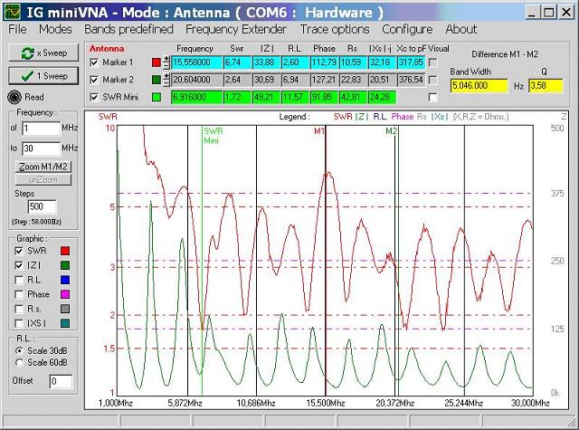
You can admire the measuring results in the diagram below. To my pleasure, the theory (EZNEC calculations and diagrams) were not so much different from the practice (measurements with miniVNA), comparing the above EZNEC diagram for 1 - 30 MHz with the diagram below. You can observe nearly identical resonant points in both diagrams! Also the diagrams with higher resolution at 80 m (next diagram) are very much alike, showing a slightly higher input impedance (green curve) or SWR (red curve). The resonance was exactly at 3.6 MHz, that is, I cut the exact length of the wire more or less by chance. The decreasing SWR levels at the higher frequencies, which I have not noticed in the EZNEC diagrams, are most probably caused by the losses of the RG58 feed line of 30 m. The calculations with EZNEC did not consider the feed line.
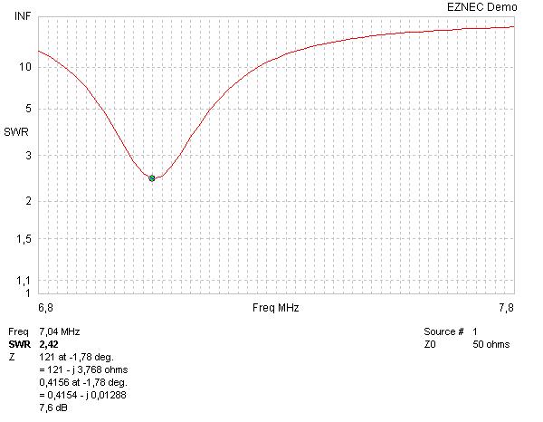
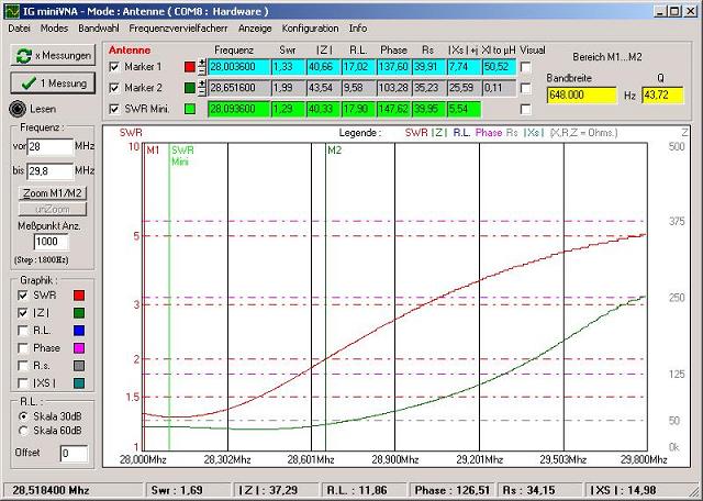
Heinz No.1 and No.2 lent me the antenna analyzer, and I could continue with my measurements without hurry. I cranked up the tower to about 16 m, and started some more measurements. As expected the resonance moved a little bit upward to 3.7 MHz, see diagrams below. To my pleasure, at 7 MHz the SWR went down to a very nice 1:1.7.
The movements of the resonance points upward was still ok for 80 m, for the higher bands they moved out of the range of the amateur bands. For 40 m it moved from the perfect 7.05 up to the not so perfect 7.28 MHz.
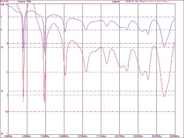
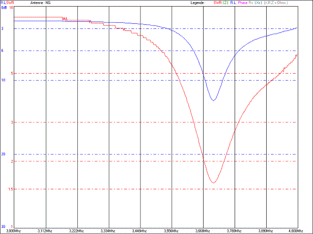
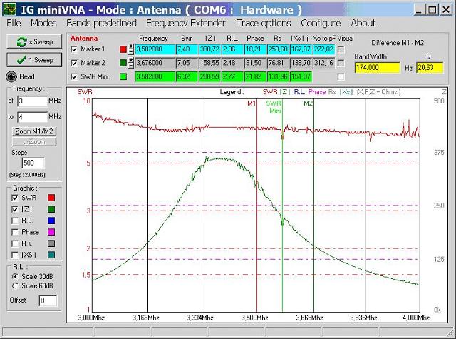
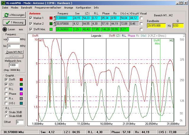
Well I let the antenna down at the side of the pine tree (less hard work than at the tower), and prolonged the wire by 2,70. This length was not the result of calculation, it was rather available as reserve which I bent together with the radiating wire. After this I pulled the antenna up at the pine tree and measured again. In the diagram below, the red curve shows the SWR, the green curve the impedance. You find the exact values of SWR and other interesting data in the text lines above the curves.
SWR and impedances at the frequency range 1 - 31 MHz
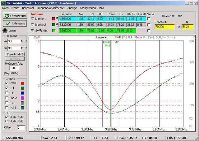
SWR and impedances 80m-Band
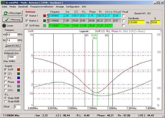
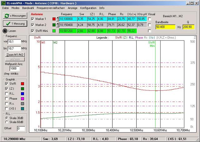
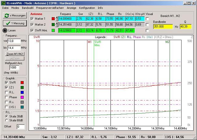
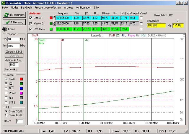
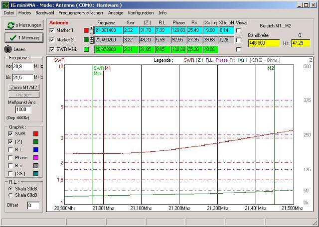
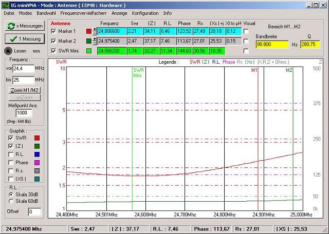
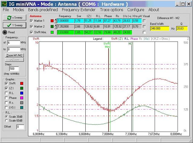
The diagrams below show the SWR and impedance values for the bands 40m - 10m.
SWR and impedances 40m-Band
SWR and impedances 30m-Band
SWR and impedances 20m-Band
SWR and impedances im 17m-Band
SWR and impedances 15m-Band
SWR and impedances 12m-Band
SWR and impedances 10m-Band
Operation with the new Delta Loop
As you can derive from the above diagrams I can operate the antenna at the 80m and 40 m bands without any additional impedance matching. The same goes for 30 m and 20 m, but the solid state transceiver decreases the output power down to 40 ... 80 watts because of the not so perfect SWR. When working with the tube amplifier I can use the full power since the tank circuits of the amplifier are able to operate with SWR values up o 1: 3. Being aware of the higher cable loss, at the receiver I noticed hardly any differences, the are negligibly at shortwave frequencies.
Admitting, that sounds rather good. It is true as long as you stay within the limits of low SWR caused by the narrow bandwidth. On the other hand, I would like to use the whole bandwidth of the 80m band. Well, I went down to the basement where I stored a lot old electronic junk, and I found a simple matchbox which I built 30 years ago. Now I am able to match all bands to a reasonable SWR. Since the SWR values are not astronomically high anyway, the box is able to compensate them, and even with the amplifier 600W I could not detect any sparking between the rather narrow condenser plates. However, I do not need an open feeder line for this multiband antenna, I can use it on all bands except 160 m. I will use the 3-element beam for the higher frequencies, of course.
I got enthusiastic after having tried my first few QSOs. At 80 m, I received several stations with signals S9 +60db. Most of the stations I worked gave me flattering reports of S9 and +20db, and this when operating barefoot with 100 W. The results on 40m were also great, many stations I could receive with S9 +40db. Admitting, the S-meter never went below S7, the base noise and QRM level was rather high. In the evening hours on 40 m, the antenna was "too good", because the commercial broadcast stations came in so strong that I only heard cross modulation signals, and hardly any signals from amateur stations. That is, the receiving end of my ICOM 706 was hopelessly overloaded. After activating the 20db attenuator, everything was perfect, the base level went down to S1, and I could hear all amateur radio stations very clearly, having many enjoyable QSOs. I could even hear VK with an S5. I worked JA with S9 reports on both sides, but I had to use the amplifier because of the pile-up competition. When exchanging station details with he other OMs, I learned that many hams were using also delta loop antennas. Hence, the Loop Skywire did not seem to be a hidden secret anymore as the ARRL Handbook, edition 1995, claimed.
Just for trial, I made a couple of QSOs on 20m to have a comparison with the 3 element beam, directed at the stations. The delta loop was an average of 2 S-units worse. I did not try 10 and 15, since the bands were dead.
Coaxial cable or open wire feeder line?
In the early stages of planning my new delta loop, I intended to use an open feeder line and a big matchbox, just like the setup at our radio club which was working excellently. However, the Handbook proposed the use of coaxial cable since the Loop Skywire works in resonance with an impedance of 50 ohm. As mentioned before, I preferred a coaxial cable, and I wanted to find out the difference of both feeder systems at practical operation. I built a simple balun 1:6 according to the ARRL Handbook and Rothammel, and I measured it with the still available antenna analyzer miniVNA to prove the frequency and transformation properties. At the next club meeting I connected the feeder line of the club delta loop to the antenna analyzer via the balun, with the measuring results below:
Delta-Loop at the club G25:
For comparison again the measurements of the delta loop at my house:
Rather approximately, the curves of both antennas looked similar, however the SWR of the 80m band was a lot worse at the club loop. I also detected some more resonance points not corresponding to a multiple of the 3.5 MHz base frequency. The next diagrams show the SWR and impedance curves of the club antenna in higher resolution.
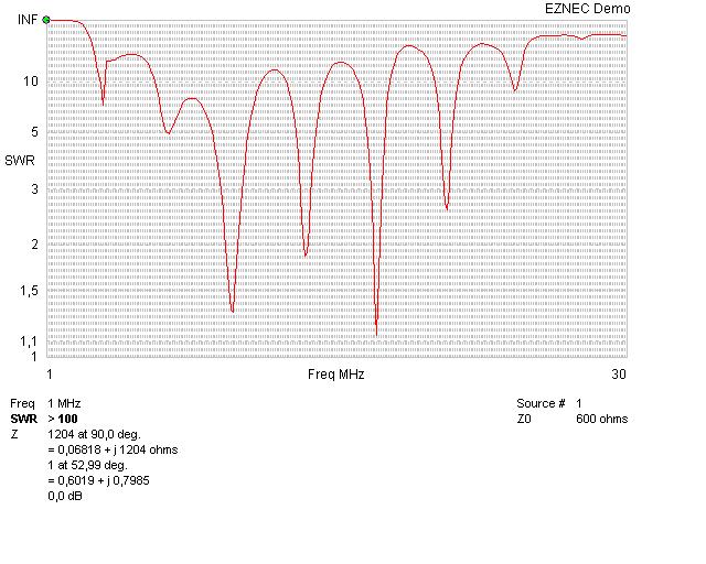
In any case, the delta loop at my house had a lot better values. Where does the miserable SWR value at 80 m at the club loop come from? In the beginning of my calculations with EZNEC, I already noticed the differences of the SWR curves at impedance values of 50 and 200 Ohms. The open feeder line at the club most probably has an impedance of about 600 Ohms (1.5 mm wire, distance 100mm). In consideration of these values I let EZNEC calculate the values at an impedance of 600 Ohms, see the result below.
Well, I was happy that I was not mistaken with my measurement with he homemade balun and the rather guessed impedance value of the feeder line of the club antenna. EZNEC confirms that the lower frequencies show a worse SWR when increasing the impedance, but improving the values for higher frequencies. Using the big matchbox you can match the impedance at the side of the transceiver, and the cable losses are little when using open feeder lines. On the other hand, I had reasonable SWR values without matchbox and with the preferred coaxial cable at my own delta loop.
Result, Summary
The Loop Skywire, with a triangle shape called Delta Loop Antenna, is an easy to build multiband antenna, without the necessity of traps or coils, using just simple wire. Principally an impedance matching is not necessary. Because of the narrow bandwidth at 80 m, a simple matchbox can help to use the complete bandwidth of the respective band when using transistor transceivers. All OMs owning a plot of 400 sqm or bigger are in the position to built a full size loop antenna for 80 and 40 m. Depending of the shape of the plot you can built it as a square or triangle. You can feed the loop antenna with regular coaxial cable (RG58/U), a an open feeder line with all its complications to construct and to install, as well as a big matchbox with symmetrical output, is not necessary. A big matchbox and open feeder line make sense only if you want to operate a wire antenna out of resonance and impedances far away from 50 Ohm. In this case the losses of the coaxial cable would be too high, the open feeder line has rather small losses. My Delta Loop Antenna is resonant at 80m and 40m with good impedance and SWR values.
The complete project was a lot of fun, since not only the result was very encouraging, also the way to the finish line was very interesting . The first time in my life I used an antenna calculations program and an antenna analyzer, the whole matter was a lot simpler than I thought before. Many thanks also to DD9KA and DL9NDG (Heinz No.1 and No.2) for their support.
Karl, DK5EC
dk5ec @ darc.de